High-Performance Piling Drivers:
Global Infrastructure Standards 2026
“DEFINING EXCELLENCE IN HYDRAULIC PILE HAMMERS AND VIBRATORY KINEMATICS”
“Better Result Using this Construction Equipment (BRUCE). In 2026, a piling driver is not judged by raw impact alone, but by its ability to integrate into complex geotechnical ecosystems—balancing energy efficiency, safety, and ESG compliance.”
01. Global Piling Drivers: The 2026 Engineering Shift
Modern infrastructure projects require piling drivers that go beyond traditional capacity. As urban centers expand and bridge spans increase, the demand for equipment that combines high torque with digital repeatability has reached a critical peak. Today, a world-class piling partner must offer more than just machinery; they must provide verified Energy Transfer Ratios (ETR) and ISO-9001 certified reliability across 80+ countries.
The 2026 landscape recognizes three dominant piling driver categories, each suited to distinct geotechnical and structural conditions:
| Driver Type | Best Application | ETR Range | Noise / Vibration |
|---|---|---|---|
| Hydraulic Impact Hammer | Bearing piles, dense strata, bridge foundations | 85–98% | Moderate / Intermittent |
| Vibratory Hammer | Sheet piles, H-piles, wick drain installation | N/A (frequency-based) | Low / Continuous |
| Hydraulic Press-In | Noise-sensitive urban zones, underpinning | Near 100% (static) | Minimal / Silent |
Data Logging as a Contractual Requirement
Selection among these categories is no longer a purely mechanical decision. In 2026, federal bridge bid specifications reference AASHTO LRFD Bridge Design and FHWA Deep Foundation guidelines. As a result, contractors must now submit pre-construction wave equation analyses (WEAP). Therefore, the instrument-grade data logging capability of modern piling drivers has become a contractual necessity, not an optional upgrade.
Direct Technical Consultation
Are you preparing a bid for a major infrastructure project? Secure 2026-standard equipment with full factory support.
Get an Expert QuoteWhy Factory-Certified Equipment Matters
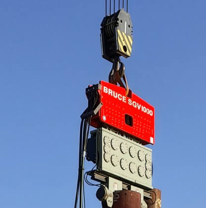
BRUCE Piling Equipment (Shinsegae Powerquip) has pioneered this shift for over 27 years. By focusing on “Maintenance-Friendly Design” and “Powerful Dynamic Components,” we ensure your fleet remains active in the most challenging strata. Consequently, whether onshore or offshore, new piling drivers are the only assets capable of satisfying real-time data logging requirements on modern federal bridge bids.
A key performance indicator is the Rated Capacity Utilization (RCU). This metric measures actual field output against the manufacturer’s rated maximum. In practice, factory-certified piling drivers consistently achieve RCU values above 92%. By contrast, refurbished or used equipment frequently falls below 75% due to hydraulic seal degradation and mechanical wear at the ram guide system.
02. What is Vibro? Harmonic Soil Liquefaction Explained
A common question for project auditors and junior geotechnical engineers is: what is vibro? At its core, a vibratory hammer is a high-frequency kinetic tool that rotates eccentric weights to induce localized soil liquefaction around the pile shaft. By temporarily neutralizing the effective stress between soil particles, the pile penetrates the strata driven by its own self-weight and the hammer’s centrifugal force—without the destructive impact cycles of a drop or diesel hammer.
The Two Key Variables: VPM and Eccentric Moment
The physics of vibratory pile driving are governed by two primary variables: Vibrations Per Minute (VPM) and Eccentric Moment (kgm). Together, these determine the amplitude of vertical oscillation. Higher eccentric moments produce larger amplitudes. These are more effective in cohesionless granular soils such as sand and gravel. In contrast, lower amplitudes at higher frequencies are preferred in soft clays, where excessive displacement can cause smear zone effects that degrade long-term pile-skin friction.
Low-Frequency Range
800–1,200 VPM
High eccentric moment. Suited for dense granular soils, H-piles, and heavy tubular steel casings. Penetrates competent gravels and dense sands effectively.
High-Frequency Range
1,600–2,400 VPM
Reduced eccentric moment. Ideal for sheet piles in soft clays, wick drain mandrel insertion, and vibration-sensitive environments near existing structures.
Balanced Double Side Eccentric Technology
In 2026, the efficiency of this process is governed by the “Balanced Double Side Eccentric” concept. This configuration pairs two counter-rotating eccentric mass assemblies on opposing sides of the powerhead. As a result, 100% of generated centrifugal force is channelled vertically into the pile. Lateral forces cancel out entirely. This protects the carrier boom from the destructive lateral resonance commonly observed in older, poorly synchronized vibratory units.
Variable Eccentric Moment (VEM) Control
Variable eccentric moment (VEM) technology is now standard on high-specification equipment. It further refines this process. By adjusting the angular offset between the eccentric weights during operation, the operator can ramp amplitude from zero to maximum while the hammer runs at full VPM. Consequently, this eliminates the resonance crossover zone on startup and shutdown. That advantage is critical when driving adjacent to existing foundations or buried utilities.
For specialized urban shoring applications requiring confined-space operation, this technology is further enhanced by side-grip kinematics, which you can explore in our Urban Side Grip Guide.
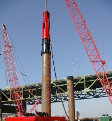
03. Hydraulic Pile Hammers: Precision Impact Dynamics
Hydraulic pile hammers operate on a fundamentally different principle from vibratory technology. Controlled, high-energy single impacts replace continuous oscillation. A hydraulic cylinder accelerates a ram—typically 3 to 20 metric tonnes—to a precisely programmed stroke height. It then releases the ram onto the pile head cushion. The result is a deterministic, measurable blow energy at every stroke.
Real-Time Data Logging and Compliance
This measurability is the defining commercial advantage of hydraulic pile hammers in 2026. Modern units are equipped with onboard stroke sensors, ram velocity transducers, and CANbus-integrated data loggers. These record every blow event in real time. Furthermore, the datasets feed directly into dynamic load test analyses (ASTM D4945). They can also be transmitted via LTE to project management platforms during active driving. As a result, both public infrastructure clients and international development bank (IDB) funded projects receive full transparency.
≥85%
Minimum ETR
2026 Specification
±0.5%
Stroke Accuracy
Hydraulic Control
40–120
Blows Per Minute
Variable Rate
Emissions Regulations Driving the Transition
The shift away from diesel hammers is not merely a preference. It reflects tightening NOx and particulate emission regulations in the European Union (Stage V), South Korea, and Southeast Asian OECD partner nations. Hydraulic pile hammers emit zero on-tool exhaust. Instead, power generation moves to a remote hydraulic power unit (HPU). This HPU can be positioned away from noise-sensitive zones or fitted with a silenced canopy enclosure.
In hard-rock and dense glacial till formations, pile refusal can occur above target depth. In these cases, high-energy variants with ram weights exceeding 15 tonnes and stroke energies above 200 kNm are required. They provide the concentrated impact force to achieve final set without overstressing the pile section. No vibratory system can replicate this capability. For this reason, hydraulic pile hammers remain the irreplaceable complement to vibratory driving in a complete foundation fleet.
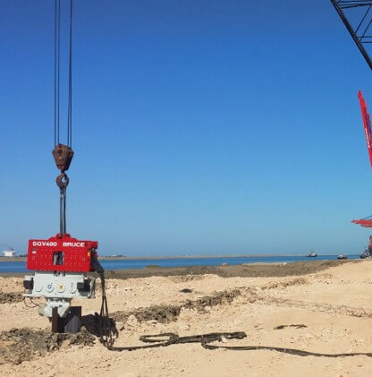
04. Specialized Soft Ground & Wick Drainage
Infrastructure on reclaimed land, coastal embankments, or marine silts depends critically on wick drainage—formally known as Prefabricated Vertical Drains (PVD)—to accelerate primary consolidation. Without active drainage pathways, excess pore water pressure dissipates at the natural rate of the clay deposit. In high-plasticity marine clays with hydraulic conductivity below 10⁻⁹ m/s, that process can take years or even decades.
How Wick Drains Shorten the Drainage Path
Wick drains solve this by shortening the drainage path from vertical to horizontal. Drain spacing is typically 1.0–1.5 m in a triangular pattern. The geotextile filter jacket of the PVD allows pore water to enter the channelled core. At the same time, it prevents fine particle migration. However, this balance is only maintained if the drain is installed without kinking, smearing, or lateral displacement.
“Wick drainage efficiency is a byproduct of installation frequency. By utilizing the specific VPM of a BRUCE driver, contractors can ensure perfect PVD verticality and maximize the geotechnical recovery of soft ground assets.”
Vibratory Installation vs. Static Push
Many contractors still rely on static push installation with a conventional mandrel frame. However, the 2026 benchmark for high-volume PVD projects is high-speed vibratory driving of wick drains. By coupling the PVD mandrel directly to the vibratory powerhead, penetration rates increase by 35–45% in soft to medium clays. Moreover, verticality control is superior compared to static push. Critically, the low eccentric moment setting avoids smear zone enlargement that has historically been associated with high-amplitude driving in sensitive clays.
PVD Installation Parameter Guide — 2026 Standard
Drain Spacing
1.0–1.5 m (triangular grid)
Reduces consolidation time by 60–80%
Installation VPM
1,400–1,800 VPM (soft clay)
Low amplitude to control smear zone
Mandrel Cross-Section
Rhombus or rectangular preferred
Minimizes disturbed zone radius
Verticality Tolerance
≤1:50 (2%) per ISO 22477-1
Exceeding this folds drain filter jacket
Post-installation, settlement monitoring using inclinometers and piezometers confirms the accelerated consolidation curve. On projects with a fixed surcharge preload schedule, speed is everything. Therefore, the installation advantage of vibratory wick drain driving directly translates to schedule compression. This is often the single most valuable commercial outcome for the project owner.
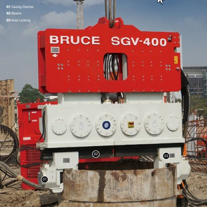
05. High-End Clamping & Components
The most common point of failure on any vibratory piling site is the hydraulic clamp. It operates under continuous vibration, elevated clamping pressures (typically 200–350 bar), and cyclic thermal loading from hydraulic oil circulation. As a result, the clamp assembly is arguably the highest-stress component in the entire drivetrain. In 2026, “standard” is no longer sufficient for high-cycle or offshore applications.
Material Specification for High-Cycle Performance
High-performance projects require hydraulic clamps manufactured from alloy cast steel—specifically GS-25CrMo4 or equivalent. The minimum hardness at the jaw contact surface must be 280–320 HBW. This specification resists abrasive wear from pile surface scale. Moreover, it prevents the impact-fatigue cracking that propagates from stress concentrations at the jaw-to-body interface in lower-grade castings.
Jaw Geometry and Pile Section Matching
Whether dealing with sheet piles (AZ, AU, PU sections), casing, or H-beams (HP and UC profiles), jaw geometry must match the pile section precisely. Oversized or mismatched jaws create stress concentrations. These crack the pile flange within a few hundred blows. On large-diameter driven pipe piles, section replacement is not contractually possible—so such failures are extremely costly. For this reason, we strictly provide new factory-certified hydraulic clamp components to ensure the Energy Transfer Ratio (ETR) is not dissipated through mechanical “play” at the pile head.
Global Operations FAQ
Equipment Selection
Q: Why are hydraulic pile hammers preferred over diesel for bridge projects?
Q: What soil conditions are unsuitable for vibratory piling drivers?
Multi-Task Applications
Q: Can your vibratory hammers handle both wick drainage and sheet piling?
Technical Specifications
Q: How is hydraulic clamp pressure specified for different pile types?