2026 Piling Equipment Engineering Guide
Hydraulic Clamp for Vibratory Hammer:
Fail-Safe Piling Standards 2026
CLAMPING FORCE CALCULATION · POCV ENGINEERING · JAW ALLOY STANDARDS · OSHA & ISO COMPLIANCE
“The integrity of a vibratory piling operation is determined at the jaw-to-pile interface. In 2026, the hydraulic clamp is the primary mechanical safety barrier between a controlled drive cycle and a free-projectile incident. Alloy-cast structural resilience and integrated check valves are not optional upgrades — they are the minimum engineering standard.”
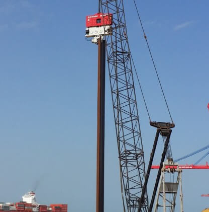
In vibratory pile driving, the hydraulic clamp is the mechanical link that transfers centrifugal force from the eccentric gearbox directly into the pile. It determines whether that energy is productive — reaching the soil interface to overcome skin friction — or dissipated as heat, noise, and mechanical wear at the connection point. A poorly specified or worn clamp does not just pose a safety risk. It directly degrades drive performance and increases project cost on every linear meter driven.
This 2026 guide covers the full engineering scope of hydraulic clamp design for vibratory hammers: clamping force calculation from first principles, pilot-operated check valve (POCV) function and legal requirements, jaw alloy material specifications, failure mode analysis, and a five-step field audit protocol. External references to ISO, OSHA, and FHWA standards are cited throughout.
01. The Physics of Clamping Force & Frictional Grip
A hydraulic clamp on a vibratory hammer performs three simultaneous functions: it grips the pile section against centrifugal acceleration forces, it transmits vertical vibratory energy from the eccentric mass assembly into the pile without phase delay, and it must release the pile cleanly during extraction without residual soil adhesion locking the jaws. Failure in any one function creates a safety incident or productivity loss.
The primary engineering quantity is the clamping force — the net compressive jaw force perpendicular to the pile surface. This force creates frictional grip through the coefficient of friction (μ) between the hardened jaw teeth and the steel pile surface. In standard piling practice, μ for a hardened serrated insert on mill-scale steel is approximately 0.35–0.45. This means the jaw force must significantly exceed the net downward force on the pile (its self-weight plus the peak centrifugal force from the hammer) to prevent micro-slippage during driving.
Clamping Force Calculation — The Safety Factor Requirement
The minimum required clamping force (Fc) must satisfy this condition throughout the drive cycle:
SF = Safety Factor ≥ 1.5 (standard industry minimum)
Wpile = Pile self-weight (kN)
Fcentrifugal = Peak centrifugal force at rated VPM (kN)
As a worked example: a 12 m AZ 26-700 sheet pile at 60 kg/m (self-weight 7.1 kN) driven with a hammer producing 280 kN centrifugal force at peak VPM requires a minimum jaw force of 1.5 × (7.1 + 280) = 431 kN. Purpose-built vibratory hammer clamps in the 150–800 kN jaw force range cover this requirement with standard margin. Mismatched or undersized clamps — frequently encountered in used equipment assemblies — commonly fall outside this range for heavier pile-hammer combinations.
| Pile Section | Self-Weight (12 m) | Hammer Fc | Min Jaw Force (SF 1.5) | Clamp Class Required |
|---|---|---|---|---|
| AZ 26-700 Sheet Pile | 7.1 kN | 280 kN | 431 kN | 500 kN class |
| HP 305×110 H-Pile | 16.3 kN | 320 kN | 504 kN | 600 kN class |
| 610 mm OD Tubular Pile | 28.4 kN | 450 kN | 717 kN | 800 kN class |
| 1020 mm OD Casing Pile | 62.0 kN | 1,500 kN | 2,343 kN | 2,500 kN class |
Energy Transfer Ratio (ETR) and Jaw Contact Area
The Energy Transfer Ratio (ETR) in vibratory driving represents the proportion of the hammer’s centrifugal force that effectively reaches the soil interface. Mechanical play between the jaw and pile flange directly degrades ETR. Even 0.5 mm of jaw clearance creates a phase delay between the hammer’s eccentric cycle and the pile’s displacement response. This lag converts productive driving energy into heat and acoustic noise.
Finite element analysis of jaw-pile contact shows that contact area below 85% of the design value reduces effective force transmission by 12–18%. Practically, this means a vibratory hammer nominally rated at 840 kN centrifugal force (e.g., a standard crane-suspended model) may only deliver 690–740 kN of effective soil force with worn jaws. On a hard-driving site, this difference determines whether the pile reaches design toe level or refuses prematurely. Jaw wear is therefore not merely a safety concern — it is a direct productivity and fuel cost variable.
Related Technical Guide
The same hydraulic clamping principles apply to side-grip configurations in confined urban sites. Explore the Side Grip Vibratory Hammer Technology Guide for Urban Shoring for lateral clamp force analysis.
02. Clamp Types by Pile Section — Selection Matrix
The geometry of the jaw insert must match the pile cross-section geometry exactly. Using the wrong jaw profile is one of the most common field errors in vibratory piling — and one of the most consequential. It reduces grip area, concentrates contact stress, and creates micro-slip conditions that damage both the pile interlock and the jaw insert within a single drive sequence.
| Clamp Type | Pile Section | Jaw Profile | Key Specification |
|---|---|---|---|
| Sheet Pile Clamp (U-type) | AZ, AU, PU interlock sections | Flat parallel jaws matched to flange width | 60U to 320U series — matched to pile weight and hammer centrifugal force |
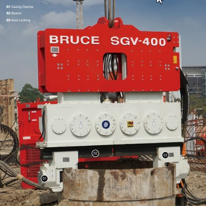
| Casing Pile Clamp (D-type) | Round steel pipe / casing piles | Concave-radius jaws matching pile OD | 2×40D to 4×160D — hydraulic auto-locking beam design |
| H-Beam Clamp | HP, UC, H-beam sections | Flat serrated jaws with flange guides | Flange guide width must match beam size precisely to prevent lateral rocking |
| Universal / Modular Clamp | Multiple section types | Interchangeable insert sets | Insert swap in under 10 minutes; full rated clamping force across all pile types |
Why Flat Jaws on Round Piles Create a Critical Hazard
When a flat-profile sheet pile jaw is used on a circular casing pile, the two jaw faces make contact along two lines rather than across a surface. The effective grip area drops by 40–60% compared to a correctly profiled concave jaw. The same hydraulic pressure that would produce 800 kN jaw force on a flat pile face produces only 320–480 kN effective grip on a circular section — potentially below the SF 1.5 minimum for a large casing pile with a high-power hammer.
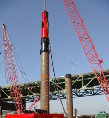
On large-diameter offshore casing piles (1,020–2,030 mm OD), where centrifugal forces from the vibratory hammer can exceed 1,500–3,000 kN, the consequences of incorrect jaw selection are severe. Purpose-built double casing pile clamps (e.g., 4×160D configuration) use multiple paired jaw beams with concave inserts to distribute clamping force across the full pile circumference. Attempting to substitute a standard sheet pile clamp on such a pile represents a critical engineering failure.
Industry Reference
The Pile Driving Contractors Association (PDCA) publishes equipment use guidelines for piling contractors in North America, including equipment selection and clamp compatibility standards. PDCA Model Safety Program documentation covers hydraulic holding device requirements for driven pile operations.
03. ISO, OSHA & International Safety Compliance
Operational safety for hydraulic clamp assemblies is governed by a layered framework: international manufacturing standards set the component-level engineering floor, while national regulations set the legal minimum for site operations. Contractors operating across the USA, UK, EU, and Asia-Pacific markets must understand which standards apply at each project jurisdiction.
The Pilot-Operated Check Valve (POCV): Engineering Function
A POCV is a hydraulically controlled non-return valve installed directly at the clamp cylinder port. In normal operation, pilot pressure from the supply circuit holds the valve open, allowing free bi-directional flow in and out of the cylinder. When supply pressure drops — due to hose rupture, fitting failure, or emergency shutdown — the pilot signal drops to zero. The POCV closes by spring force, trapping the fluid in the cylinder and maintaining full clamping pressure indefinitely. Critically, this valve is physically co-located with the cylinder head. It does not depend on any external hose. The protection exists at the exact risk point.
“A clamp without a POCV is not a holding device — it is a temporary grip. If a supply hose fails during vibratory driving, the pile becomes a free projectile. This is why ISO 4413 and OSHA 1926.603 both mandate load-holding valves on all construction holding circuits, without exception.”
FHWA and Bridge Foundation Requirements (USA)
The Federal Highway Administration (FHWA) Design and Construction of Driven Pile Foundations manual (Publication No. FHWA-NHI-16-009) is the primary US technical reference for driven pile operations on federally funded bridge and highway projects. It covers equipment selection requirements, driving system approval (DSA) procedures, and the use of dynamic monitoring equipment such as the Pile Driving Analyzer (PDA) to verify energy transfer. The hydraulic clamp specification and POCV certification are required components of the DSA submission package for vibratory piling on FHWA-funded projects.
The FHWA manual is freely available through the FHWA Geotechnical Publications Portal and is the standard reference document for pile driving engineers operating on US interstate infrastructure projects.
04. Alloy-Cast Jaw Specifications & Failure Modes
The jaw assembly operates under three simultaneous loading conditions: static clamping load (200–350 bar hydraulic pressure on the cylinder), dynamic vibratory load (cyclic inertial forces at 1,400–2,400 VPM), and thermal load (heat generated by continuous hydraulic oil circulation). As a result, material selection is not a commercial decision — it is a structural engineering requirement with direct safety implications.
Material Specification
Jaw Body Casting
GS-25CrMo4 Alloy Steel
Equivalent to ASTM A148 Grade 105-85. Bulk hardness 280–320 HBW. Superior fatigue resistance compared to grey iron GG-25, which fractures by cleavage under cyclic vibratory stress. Must be NDT tested (ultrasonic or magnetic particle inspection) to verify absence of internal porosity before delivery. GS-25CrMo4 has approximately 3× higher fatigue endurance limit than GG-25 under equivalent vibratory load spectra.
Replaceable Jaw Inserts
Induction-Hardened Tool Steel
Contact face hardness 340–400 HBW by induction hardening or tungsten carbide (WC) insert bonding. Tooth height when new: 4–6 mm. Replace when tooth height drops below 2.5 mm, or when any crown radius exceeds 1.5 mm. Insert geometry is pile-section specific — flat for sheet piles, concave-radius for tubular and casing piles. Never substitute insert types across pile profiles.
Primary Failure Modes & Engineering Root Causes
NDT Standard Reference
Non-destructive testing requirements for cast steel components are defined under ASTM A148/A148M (steel castings for structural applications) and ISO 4990 (steel castings — general technical delivery requirements). Any jaw body delivered without a mill certificate confirming chemical composition and NDT results should be rejected before site deployment.
05. Maintenance Intervals & Field Replacement Protocol
Hydraulic clamp maintenance is not an optional site activity — it is a legally required component of any ISO 9001-compliant piling equipment management system. The consequence of missed maintenance intervals is not just increased wear. It is the progressive degradation of the safety margin below the SF 1.5 minimum required by international piling standards, creating conditions for a notifiable site incident.
| Component | Check Interval | Replacement Trigger | Consequence if Missed |
|---|---|---|---|
| Jaw inserts (tooth profile) | Every 40 hr or 500 m² | Tooth height < 2.5 mm | ETR drop 12–18%; pile slip risk |
| Fastener torque | Every 40 hr | Below spec torque; fretting corrosion | Insert ejection under load |
| POCV static lock-up test | Before each project | Pressure drop > 5 bar / 10 min | Pile free-fall on hose failure |
| Hydraulic fluid condition | Every 1,000 hr | ISO 4406 class above 18/16/13 | POCV seat scoring; 4–6× higher failure rate |
| Jaw body NDT inspection | Annually or after high-energy refusal | Any visible surface cracking | Brittle fracture under vibratory load |
Hydraulic Oil Specification for Clamp Circuits
Clamp circuits containing POCVs are particularly sensitive to hydraulic fluid contamination. Particulate contamination above ISO 4406 class 18/16/13 causes accelerated scoring of the POCV poppet seat. Once scored, the valve cannot seal fully — and the clamping pressure decay rate increases until the clamp fails the 5-bar-in-10-minutes static test.
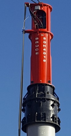
For vibratory hammer power packs and carrier auxiliary circuits, an ISO VG 46 or ISO VG 68 anti-wear hydraulic oil meeting DIN 51524 Part 2 (HLP grade) is the standard specification. For marine and offshore deployments, a biodegradable ester-based hydraulic oil meeting ISO 15380 Type HETG or HEES is required to satisfy marine environmental regulations. All BRUCE SGV series vibratory hammers are confirmed 100% compatible with biodegradable hydraulic oils meeting these classifications.
Environmental Reference
Biodegradable hydraulic oil requirements for marine and environmentally sensitive construction sites are defined under ISO 15380 (Lubricants, industrial oils and related products — Classification of categories HETG, HEPG, HEES and HEPR). The US EPA’s Vessel General Permit (VGP) framework mandates use of environmentally acceptable lubricants (EALs) in machinery that could come into contact with US navigable waters — which includes vibratory hammer hydraulic circuits deployed on marine piling projects.
06. How-To: Auditing Hydraulic Clamp Reliability
5-Step Field Protocol
This protocol should be completed before initial deployment on any new project and repeated after any equipment incident, hose replacement, or clamp jaw insert change.
STEP 1 — CALCULATE MINIMUM REQUIRED CLAMPING FORCE
Before mobilization, calculate the minimum holding force using: Fc ≥ 1.5 × (Wpile + Fcentrifugal). Obtain the hammer’s rated centrifugal force at peak VPM from the manufacturer’s specification sheet — do not estimate from nameplate power alone. Verify the clamp’s rated jaw force at the intended operating pressure exceeds your calculated value. If the clamp data plate is missing or illegible, do not deploy without a manufacturer recertification document.
STEP 2 — PERFORM STATIC PRESSURE LOCK-UP TEST
With the clamp closed on a representative pile section, pressurize the clamping circuit to rated operating pressure (250–350 bar). Shut down the hydraulic pump. Monitor circuit pressure with a calibrated digital gauge over 10 minutes. A pressure drop exceeding 5 bar indicates a leaking POCV seat or worn cylinder seal. Condemn the clamp for workshop repair. Do not continue with a reduced pressure setting as a workaround — this directly reduces jaw force below the SF 1.5 minimum.
STEP 3 — INSPECT JAW FACE AND TOOTH PROFILE
Measure tooth height on all jaw inserts with a vernier caliper. New inserts: 4–6 mm. Replace when any tooth drops below 2.5 mm or any crown radius exceeds 1.5 mm. Measure jaw contact coverage against the pile flange with a feeler gauge: ≥ 90% of the designed contact face is required. Metal smearing or plastic deformation across more than 15% of any insert tooth indicates fatigue — replace the full insert set, not individual teeth.
STEP 4 — VERIFY BOLT TORQUE AND FASTENER INTEGRITY
Verify all jaw insert retaining bolts with a calibrated torque wrench (typically 180–220 Nm for M16 Grade 10.9 fasteners with Nord-Lock washers). Inspect for fretting corrosion at the bolt-housing interface — a brown-orange powder deposit indicating micro-slip and preload loss under vibratory loading. Re-torque any bolt below specification. Inspect every 40 operating hours. Never downgrade from Grade 10.9 to Grade 8.8 bolts.
STEP 5 — TEST SAFETY INTERLOCK AND AUXILIARY CIRCUIT SYNCHRONIZATION
Using the carrier’s control system diagnostic mode, confirm the clamp-open command is electronically disabled when VPM > 0. This prevents accidental pile release during active driving. Measure clamp closing time from fully open to full rated pressure — it must not exceed 3 seconds. Closing times above 3 seconds indicate hydraulic circuit contamination, undersized auxiliary flow, or a failing directional control valve. Each condition must be rectified before production driving begins.
07. Hydraulic Clamp Engineering FAQ
Design & Selection
Q: What is the correct clamping force formula for a vibratory hammer?
Q: Can a standard hydraulic clamp be used for both pipe piles and sheet piles?
Q: How does jaw wear affect Energy Transfer Ratio (ETR)?
Safety & Compliance
Q: Why is a pilot-operated check valve (POCV) mandatory on hydraulic clamps?
Q: What alloy material should a hydraulic clamp jaw be made from?
Q: What is the correct clamping pressure for an H-pile vs. a sheet pile?
Q: How often should vibratory hammer clamp jaws be inspected on a large project?