Vibratory Hammer
A comprehensive technical reference on vibratory hammer equipment, working principle, classification, applications, and industry standards
1. Definition and Overview
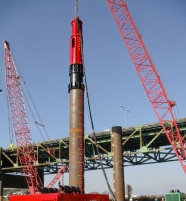
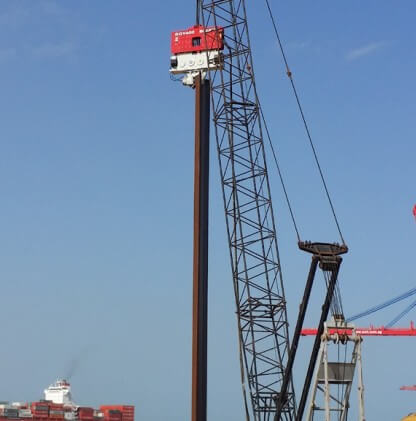
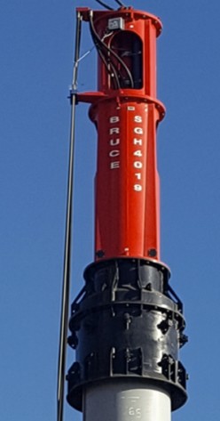
A vibratory hammer, also known as a vibro hammer or vibrodriver, is a piece of foundation construction equipment used to install and extract piles by means of induced mechanical vibration rather than repeated percussive impact. It is typically suspended from a crane or mounted directly to an excavator, and clamps onto the head of a steel sheet pile, tubular pile, H-beam, or casing to transmit vertical vibratory force along the pile axis. This vibration temporarily reduces the frictional and end-bearing resistance of the surrounding soil, allowing the pile to advance into the ground under a combination of its own weight and the applied dynamic force, or to be withdrawn under upward line pull.
Vibratory hammers are distinguished from impact pile driving hammers, which rely on repeated high-energy blows delivered by a falling ram, diesel combustion cycle, or hydraulic piston. Where impact hammers concentrate large amounts of energy into brief, discrete strikes, vibratory hammers apply continuous, lower-amplitude cyclic loading at frequencies typically ranging from roughly 1,000 to over 3,000 vibrations per minute (vpm), depending on the model and application. For a broader technical overview of vibratory installation and how it fits within the wider field of foundation piling, see this vibratory hammer guide, which addresses the equipment specifically in the context of U.S. contractor practice.
2. History and Development
The vibratory pile driving method emerged from research conducted in the Soviet Union in the late 1940s and early 1950s, where engineers observed that applying vibration to a pile during driving significantly reduced the resistance encountered in granular soils. Early vibratory drivers used simple mechanical eccentric weight arrangements and were limited in both frequency and force output compared to modern equipment. The technology was subsequently developed and commercialized in Western Europe, Japan, and the United States through the second half of the twentieth century, with hydraulic power systems progressively replacing the mechanical and electric drive systems used in earlier designs.
The introduction of hydraulically driven, variable-moment, and high-frequency vibratory hammers from the 1980s onward substantially expanded the range of soil conditions and pile sections that vibratory methods could address, and reduced the low-frequency resonance effects that had previously limited the use of vibratory driving near sensitive structures. Contemporary manufacturers, including specialist Korean, European, and North American producers, now offer vibratory hammers spanning a wide capacity range, from compact excavator-mounted units suited to light sheet piling through to large crane-suspended models capable of installing heavy tubular piles for marine and offshore applications.
3. Working Principle
A vibratory hammer generates force through pairs of counter-rotating eccentric weights housed within a gearbox. Each pair rotates in opposite directions at identical speed, synchronized by a gear train. As the weights rotate, the horizontal components of centrifugal force generated by each weight cancel one another, while the vertical components combine additively, producing a net force that oscillates purely along the vertical axis. This cancellation of horizontal force is what allows the hammer to transmit vibration efficiently along the pile without inducing damaging lateral motion in the pile or the supporting crane structure.
In granular soils, the vibration reduces the effective friction angle between soil particles surrounding the pile shaft, a phenomenon often described as temporary soil liquefaction or fluidization. This significantly lowers the skin friction resistance that would otherwise oppose pile movement, allowing the combined weight of the pile, the hammer, and the applied dynamic force to drive the pile downward. In cohesive soils such as stiff clay, the mechanism differs: rather than liquefying, the soil deforms plastically under repeated cyclic loading, and penetration is governed more by the amplitude of vibration, which determines the degree of shear strength breakdown at the pile-soil interface, than by frequency alone.
The key operating parameters that define a vibratory hammer’s performance are centrifugal force (the peak dynamic force generated at the operating frequency), eccentric moment (the product of the eccentric mass and its radius of rotation, which determines amplitude), operating frequency, and line pull capacity for extraction. A widely referenced starting rule for hammer selection is that the centrifugal force generated should be at least fifteen times the weight of the pile being driven, although this baseline is routinely adjusted upward for cohesive soils, dense granular layers, or deep embedment requirements. A detailed breakdown of these parameters and how they interact with soil conditions is available in the vibratory hammer FAQ reference.
4. Components
A vibratory hammer assembly consists of three principal structural components, supported by an external hydraulic power source and operator control system.
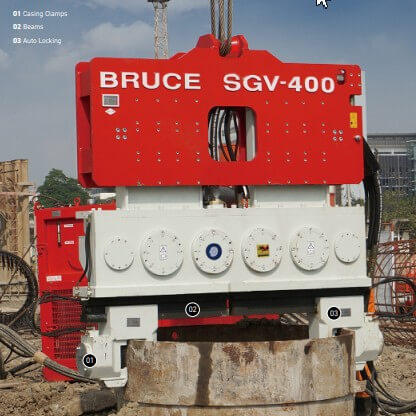
Gearbox. The gearbox houses the counter-rotating eccentric weights and the synchronizing gear train, and is the source of the vibratory force. Gearbox components are typically manufactured from precision-machined alloy steel to withstand sustained cyclic loading and to maintain the mechanical synchronization required for balanced, purely vertical oscillation over the hammer’s operating life.
Suppressor (vibration damper). Mounted above the gearbox, the suppressor assembly mechanically isolates the vibrating gearbox from the crane hook or excavator boom, using elastomer rubber elements that absorb and dissipate the majority of the vibrational energy that would otherwise transmit into the supporting equipment. Suppressor condition directly affects both equipment longevity and the amount of ground-borne vibration generated at the surface, making it a frequent subject of technical documentation on projects with strict vibration compliance requirements.
Clamp. The clamp assembly grips the pile head during both driving and extraction. Hydraulic clamp cylinders apply and maintain gripping force, typically through hardened, high-strength alloy steel jaws shaped to match common sheet pile, H-beam, and tubular pile profiles. A check valve integrated into the clamp circuit maintains clamping pressure independently of hose pressure, which is a critical safety feature preventing pile drop in the event of a hydraulic line failure.
Power pack and remote pendant. Crane-suspended vibratory hammers are powered by a separate hydraulic power pack, typically diesel-driven, connected via hydraulic hoses. Excavator-mounted models draw hydraulic power directly from the host excavator’s auxiliary circuit, eliminating the need for a separate power source. In both configurations, the operator controls the hammer through a remote pendant, which typically provides real-time adjustment of hydraulic flow and therefore centrifugal force and amplitude, allowing the operator to manage penetration rate and vibration output without stopping the drive cycle.
5. Classification and Types
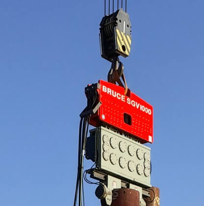
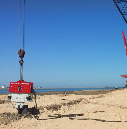
By mounting configuration. Crane-suspended vibratory hammers are attached to a crane via a suspension bracket and are used for large sheet pile sections, deep embedment, and heavy tubular or casing piles where the required centrifugal force and vertical clearance exceed excavator-mounted capacity. Excavator-mounted vibratory hammers attach directly to an excavator arm, connecting to the host machine’s auxiliary hydraulic circuit, and are favored for lighter sheet piling, confined access sites, and projects where eliminating a separate crane reduces mobilization cost and equipment footprint.
By frequency class. Standard-frequency vibratory hammers typically operate in the range of roughly 1,000 to 2,000 vpm and are suited to general sheet piling and casing work. High-frequency models, which can exceed 3,000 vpm, pass through the resonant frequency range of most structures more quickly during startup and shutdown, reducing the risk of resonance-induced vibration damage to nearby buildings, which makes them a common choice for urban and vibration-sensitive projects.
By clamping method. Top-clamp vibratory hammers, the most common configuration, grip the pile from above and require overhead clearance for the hammer body and leader system. Side-grip vibratory hammers clamp the pile laterally and transmit force through the excavator arm rather than crane suspension, allowing installation in low-headroom environments such as beneath existing structures or overhead utility corridors where top-clamp systems cannot physically operate.
By variable-moment capability. Fixed-moment vibratory hammers operate at a single eccentric moment setting determined by the physical weight configuration. Variable-moment hammers allow the operator to adjust eccentric moment during operation, typically by hydraulically shifting eccentric weight elements, enabling the hammer to pass through resonant frequencies at reduced amplitude during startup and shutdown before increasing to full driving force, further reducing transmitted vibration.
6. Comparison with Impact Hammers
Vibratory and impact hammers are complementary rather than directly competing technologies, and many pile installation programs use both in sequence. Vibratory hammers generally achieve substantially faster penetration rates in loose to medium-dense granular soils, produce significantly lower noise and ground-borne vibration, generate no combustion emissions during operation, and can extract piles using the same equipment used for installation, which impact hammers cannot do without specialized extraction attachments. These characteristics make vibratory hammers the preferred method for temporary works, urban sites, and environmentally sensitive locations.
Impact hammers, by contrast, are generally required to achieve the bearing capacity verification demanded for permanent load-bearing piles, since the blow count and energy transfer recorded during impact driving provide the dynamic testing data referenced in structural design codes such as ASTM D4945 in the United States. Impact hammers also remain the more reliable method for penetrating dense granular layers, weathered rock, and stiff cohesive soils where vibratory penetration reaches practical refusal. Consequently, many foundation and marine projects use vibratory hammers for initial penetration and positioning, transitioning to impact hammers for final set in high-resistance strata, an approach documented in detail in the BRUCE technical reference on vibro hammer operating principles.
7. Selection Criteria
Selecting an appropriately sized vibratory hammer for a given project requires evaluating several interdependent parameters against the specific pile section, soil profile, and site constraints, rather than applying a single generic specification across all conditions.
Pile weight and section. Centrifugal force requirements scale with pile weight, with the commonly cited baseline of at least fifteen times pile weight serving as a starting reference that is adjusted upward for challenging soil conditions.
Soil profile. Loose to medium-dense granular soils generally respond well to standard centrifugal force and frequency ranges. Dense sand, gravel, and cohesive clay layers typically require higher eccentric moment to achieve adequate amplitude and maintain penetration rate, since vibration alone does not liquefy cohesive soils in the same manner as granular material.
Embedment depth. Deep embedment requirements demand equipment with sufficient centrifugal force reserve to overcome accumulated skin friction along the full pile length, not just the resistance encountered near the surface.
Mounting and access constraints. Site access, overhead clearance, and the availability of a crane versus an excavator-only fleet determine whether a crane-suspended or excavator-mounted configuration, and whether a top-clamp or side-grip system, is appropriate.
Vibration sensitivity of the surrounding environment. Projects near occupied structures, heritage buildings, or vibration-sensitive infrastructure typically favor high-frequency or variable-moment equipment capable of managing transmitted ground vibration within regulatory or contractual limits.
8. Applications
Vibratory hammers are used across a wide range of civil, marine, and infrastructure construction sectors. Common applications include installation and extraction of temporary sheet pile cofferdams for bridge pier and foundation construction; permanent and temporary sheet pile retaining walls for highway, rail, and building excavation support; steel casing installation for drilled shaft and caisson foundations; marine and port infrastructure, including quay wall sheet piling, combi-wall primary pile installation, and breakwater and seawall foundations; offshore wind foundation pre-piling and jacket pin pile installation; and rail and transit infrastructure shoring, including track-side cofferdams and station box temporary works.
In the United States specifically, vibratory hammers are widely used on DOT-funded highway bridge replacement programs, USACE-regulated coastal flood defense and hurricane barrier construction, and urban rail and utility infrastructure projects where noise and vibration limits, combined with productivity requirements, favor vibratory installation over impact methods. Field practices and case-specific guidance for these applications are addressed in the vibratory hammer guide for U.S. pile driving.
9. Standards and Regulatory Framework
Vibratory hammer use is governed indirectly through the piling design and construction standards applicable in each jurisdiction, rather than through a dedicated equipment-specific standard. In the United States, ASTM D4945 governs high-strain dynamic testing of deep foundations, which is typically applied to impact-driven bearing piles rather than vibratory sheet piling directly, but frequently applies on the same project where both methods are used. AASHTO LRFD Bridge Design Specifications provide the structural framework referenced on DOT-funded bridge and highway projects. USACE Section 404 and Section 10 permits govern in-water piling on navigable waterways, commonly including equipment-specific conditions such as biodegradable hydraulic fluid requirements and underwater noise limits.
Internationally, the PIANC (World Association for Waterborne Transport Infrastructure) publishes widely referenced guidance for port and marine structure design, EN 12699 governs displacement pile execution in the European Union, and AS 2159 serves as the mandatory Australian standard for piling design and installation. Construction vibration limits are commonly assessed against DIN 4150-3 or BS 7385-2, both of which provide frequency-dependent guide values for cosmetic building damage risk, applied in combination with local or project-specific environmental management plan conditions.
10. Environmental and Safety Considerations
Vibratory hammers generate substantially lower airborne noise and underwater acoustic pressure than impact hammers, which has made them the preferred method on projects subject to marine fauna protection requirements, urban noise ordinances, and construction environmental management plans. Biodegradable hydraulic oil compatibility is an increasingly common specification requirement on projects involving in-water or environmentally sensitive plant operation, driven by pollution prevention conditions attached to permits issued by agencies such as USACE in the United States or equivalent authorities elsewhere.
Ground-borne vibration transmitted during driving remains a primary safety and compliance consideration on projects near existing structures, buried utilities, or sensitive infrastructure. Continuous peak particle velocity (PPV) monitoring, combined with an operator’s ability to adjust centrifugal force and amplitude in real time via the remote control pendant, is the standard operational method for maintaining compliance with vibration trigger levels specified in a project’s environmental management plan or permit conditions without stopping the drive cycle unnecessarily.
11. Industry Outlook
Demand for vibratory hammer equipment continues to expand alongside growth in coastal flood defense infrastructure, offshore wind foundation installation, and urban rail and basement construction programs across North America, Europe, and the Asia-Pacific region. Manufacturers continue to develop higher-frequency, variable-moment, and remotely monitored equipment to address increasingly stringent vibration and noise compliance requirements, alongside compatibility with biodegradable hydraulic fluids and expanded centrifugal force ranges to accommodate larger pile sections used on major infrastructure and marine energy projects.
Manufacturers such as BRUCE (produced by Shinsegae Powerquip Industrial Co., Ltd.) supply vibratory hammer equipment spanning excavator-mounted and crane-suspended configurations for markets including the United States, where technical specification, project consultation, and equipment sourcing inquiries can be directed to the BRUCE engineering desk. Full model specifications, including the SGV series covering centrifugal forces from 510 kN to 4,610 kN, are documented at powerquip.co.kr/products/vibro-hammer/features-2.