Soft Ground Stabilization:
High-Speed Wick Drainage Tech 2026
“ACCELERATING CONSOLIDATION THROUGH HIGH-FREQUENCY PVD INSTALLATION”
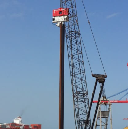
“Efficient wick drainage is not just about the material—it is about installation frequency. In 2026, using high-speed vibratory piling drivers for PVD placement ensures zero-kink verticality and maximizes the geotechnical recovery of reclaimed land.”
01. The Physics of Wick Drainage & Consolidation
Infrastructure on reclaimed land or marine silts depends critically on wick drainage—formally known as Prefabricated Vertical Drains (PVD)—to accelerate primary consolidation. In its natural state, saturated clay consolidates through Terzaghi’s one-dimensional drainage model. Water must travel the full height of the deposit before pore pressures equalize. In high-plasticity marine clays with a coefficient of consolidation (cv) as low as 0.5–2.0 m²/year, that process can take 15–30 years under a typical embankment surcharge.
How PVDs Radically Shorten Consolidation Time
Wick drains solve this by converting vertical drainage into radial (horizontal) drainage. The drainage path length drops from the full deposit depth (H) to the drain spacing radius (re). In a triangular grid at 1.2 m spacing, that effective radius is approximately 0.65 m. This geometry change, combined with the typically higher horizontal permeability (kh) of layered clays—often 2–10× greater than vertical permeability—reduces consolidation time by 70–90%.
| Scenario | Drainage Path | 90% Consolidation Time | Practical Outcome |
|---|---|---|---|
| No PVD (natural vertical) | H = 15 m | 18–25 years | Impractical for most projects |
| PVD at 1.5 m triangular grid | re ≈ 0.83 m | 8–14 months | Feasible with standard preload |
| PVD at 1.0 m triangular grid | re ≈ 0.56 m | 3–6 months | Fast-track schedule compliance |
The theoretical basis for these estimates is Barron’s equal-strain solution (1948), later refined by Hansbo (1981). According to this model, the average degree of radial consolidation (Ur) depends on the drain spacing ratio n = re/rw, where rw is the equivalent drain radius. Furthermore, as n decreases—meaning drains are spaced more closely—the consolidation curve steepens dramatically. In practice, therefore, halving drain spacing from 1.5 m to 0.75 m reduces the time to 90% consolidation by approximately four times.
TECHNICAL PILLAR HUB
Does your project require both soft ground stabilization and confined urban shoring? Review the Side Grip Vibratory Hammer Technology Guide for Urban Shoring — the same high-frequency driver technology applies to both applications.
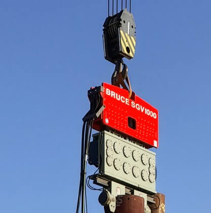
The efficiency of this process is further governed by two performance-limiting factors: Well Resistance and the Smear Zone. Both are directly controlled by the installation method. High-performance projects in 2026 therefore use vibratory installation to minimize these effects. Using new piling machinery with factory-calibrated frequencies ensures the mandrel penetrates the soil with minimal lateral disturbance.
02. Smear Zone & Well Resistance: The Two Efficiency Killers
Even a perfectly designed PVD grid can underperform if installation quality is poor. Two mechanisms account for most real-world efficiency losses. Understanding and controlling them is, consequently, the primary technical objective of any wick drainage project.
The Smear Zone: Installation Damage Around the Drain
When a mandrel is pushed or driven into soft clay, it displaces and remolds the surrounding soil. The result is a cylindrical zone of reduced horizontal permeability around each drain. This is known as the smear zone. Within this zone, kh may drop to near the vertical permeability (kv), eliminating the horizontal drainage advantage entirely for that radius.
Smear Zone Radius (ds)
2–4 × dm
Where dm = equivalent mandrel diameter. Rhombus mandrels (60×100 mm) produce smaller smear zones than circular mandrels of equivalent cross-section area.
Permeability Ratio in Smear Zone
kh/ks = 2–8
The horizontal permeability of undisturbed clay (kh) vs. the smear zone (ks). Higher ratios indicate greater installation damage and lower drainage efficiency.
Research by Indraratna & Redana (1998) and subsequent field studies confirm that mandrel shape has a greater effect on smear zone extent than mandrel size. Specifically, a rhombus-section mandrel (60 mm × 100 mm) produces a smear zone radius of approximately 2× the equivalent circular mandrel diameter. In contrast, a circular mandrel of the same cross-section produces a smear zone radius of 3–4×. Moreover, static push installation typically generates 20–40% larger smear zones than vibratory driving at equivalent mandrel sizes, because the repeated micro-reversals of vibratory penetration reduce the cumulative shear displacement in the surrounding clay.
Well Resistance: Flow Capacity of the Drain Core
Well resistance occurs when the drain channel cannot carry the pore water fast enough to the horizontal drainage blanket at the surface. It becomes significant at depths exceeding 20 m, or when the drain’s discharge capacity (qw) falls below approximately 100 m³/year under the applied confining pressure. Standard PVD products tested at 350 kPa confining stress typically retain 80–120 m³/year. However, kinked or folded drains—which occur when installation verticality exceeds 1:50—can reduce qw by 60–80%, making well resistance the dominant failure mode on deep deposits.
“The combined effect of smear zone and well resistance can reduce the theoretical degree of consolidation at 12 months by 30–50 percentage points. Therefore, installation method is not a secondary consideration—it is the primary performance variable on any wick drainage project.”
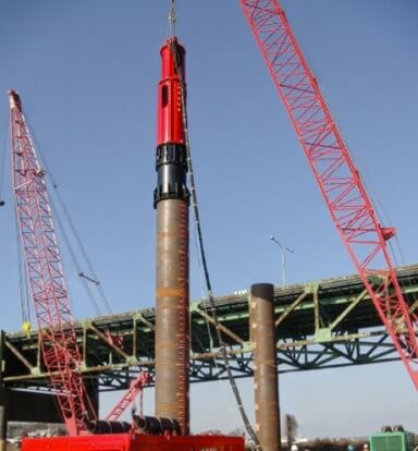
03. Vibratory Kinematics in High-Speed PVD Installation
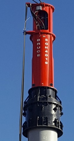
Many contractors still rely on static push-in methods for wick drains. However, the 2026 benchmark for high-volume PVD projects is high-frequency vibratory driving. By coupling the mandrel to a vibratory powerhead operating at 1,400–1,800 VPM, the tip of the mandrel undergoes rapid micro-reversals of vertical displacement. These micro-reversals temporarily reduce the effective shear stress at the clay-mandrel interface. As a result, penetration resistance drops by 40–60% compared to static push in identical soil conditions.
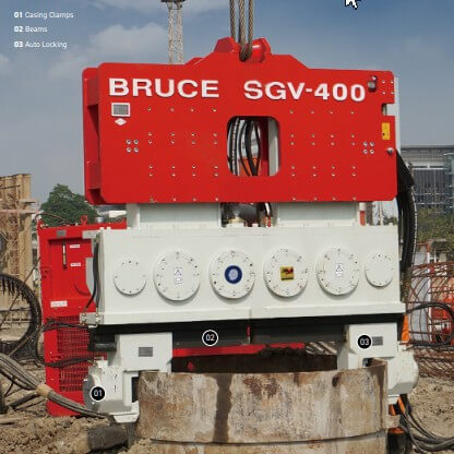
Why Low Eccentric Moment is Critical for PVD Work
Vibratory PVD installation requires a specific amplitude setting. Unlike sheet pile driving—where higher eccentric moments accelerate penetration in dense soils—wick drain installation demands low eccentric moment at high frequency. The target peak-to-peak displacement amplitude at the mandrel tip should be 3–8 mm. Amplitudes above 10 mm generate excessive lateral soil displacement, enlarging the smear zone beyond the theoretical optimum and negating the speed advantage.
PVD Vibratory Installation Parameter Guide — 2026 Standard
Operating Frequency
1,400–1,800 VPM
Avoid natural resonance of silt (typically 800–1,100 VPM)
Mandrel Tip Amplitude
3–8 mm peak-to-peak
Exceeding 10 mm enlarges smear zone
Penetration Rate
0.3–0.8 m/s in soft clay
Slow down ≤ 0.2 m/s through dense crusts
Verticality Tolerance
≤ 1:50 (2%) per ISO 22477-1
Beyond this, the PVD filter jacket folds
Mandrel Section
Rhombus 60×100 mm preferred
Minimizes ds/dm ratio vs. circular
Withdrawal Speed
0.5–1.0 m/s (vibration ON)
Vibrating during withdrawal reduces heave and anchor pull-out
This kinetic energy approach is also critical when penetrating over-consolidated surface crusts or thin sand lenses. These layers frequently cause static mandrels to buckle or deflect laterally. Moreover, a balanced eccentric moment—where counter-rotating masses cancel all lateral force—maintains mandrel verticality through these transitions. Consequently, the drain reaches the specified design depth without ‘corkscrewing’ through the stratigraphy.
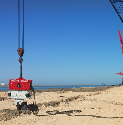
04. Consolidation Strategies for Marine Silt
In harbor developments and coastal reclamation, wick drainage must handle high hydrostatic pressures and variable stratigraphy. The combination of surcharge pre-loading and PVD installation requires a carefully staged approach. Furthermore, leading geotechnical firms in 2026 prioritize equipment that logs installation depth and penetration force in real time. This creates a digital as-built record for every drain.
Surcharge Design and Staged Loading
PVDs do not consolidate the soil by themselves. They only shorten the drainage path. Therefore, a vertical stress increment—the surcharge—must be applied to drive consolidation. In practice, three surcharge strategies are used: preload fill (permanent or temporary), vacuum preloading, and combined vacuum-fill. The combined method is increasingly favored on soft marine deposits because it applies an equivalent consolidation pressure of 80–100 kPa through vacuum alone, without adding fill weight that could trigger bearing capacity failure in very soft clay (cu < 15 kPa).
Monitoring: How to Read the Consolidation Curve
Effective monitoring confirms that the theoretical consolidation curve is being achieved in the field. Three instruments are essential. First, vibrating wire piezometers installed at multiple depths confirm the dissipation of excess pore water pressure (EPWP). Second, settlement plates at the ground surface track primary consolidation settlement against time. Third, inclinometers at the surcharge perimeter detect lateral movement indicating incipient slope failure. For the full federal instrumentation and monitoring protocol, refer to the FHWA Geotechnical Engineering Resource Center, which publishes the governing design standards for PVD-assisted consolidation on federally funded projects.
“We strictly recommend new factory-supported assets for wick drain projects because the maintenance history of used equipment is rarely verifiable. A used driver with inconsistent frequency can damage the PVD sleeve, rendering the entire drainage field ineffective.”
How-To: Calibrating Piling Drivers for Wick Drain Efficiency
STEP 1 — AUDIT SOIL SHEAR STRENGTH AND STRATIGRAPHY
Before mobilization, analyze the CPT (Cone Penetration Test) and laboratory consolidation test logs. Identify the following: (a) the undrained shear strength profile (cu) to confirm static installation is feasible in the surface crust; (b) the coefficient of horizontal consolidation (ch) to validate drain spacing; (c) the OCR (Overconsolidation Ratio) at each depth—layers with OCR > 2 will require a higher eccentric moment to initiate mandrel penetration. This pre-project analysis directly sets the VPM range and eccentric moment required for your specific equipment.
STEP 2 — PERFORM A TRIAL INSTALLATION SECTION
Before full production, install a trial section of 20–30 drains at the design spacing. During this trial, record penetration force vs. depth at 0.5 m intervals. Specifically, flag any depth where penetration force exceeds 15 kN—this indicates a stiff layer requiring frequency or eccentric moment adjustment. After the trial, excavate two to three drains to visually inspect the filter jacket for kinking or smear contamination. The trial section data, consequently, forms the calibration baseline for the entire production phase.
STEP 3 — SYNCHRONIZE MANDREL FREQUENCY TO SOIL TYPE
Calibrate the driver’s VPM to operate above the natural resonance frequency of the soft silt layers (typically 800–1,100 VPM). Operating within this resonance band amplifies lateral ground movement around the rig. Moreover, it increases the risk of unwanted subsidence under adjacent completed surcharge areas. Target 1,400–1,800 VPM for most soft to medium marine clays. In contrast, for over-consolidated crust layers in the top 2–4 m, briefly increasing VPM to 2,000+ VPM while reducing penetration speed to < 0.2 m/s allows controlled breakthrough without excessive lateral smear.
STEP 4 — VERIFY AUTO-CALIBRATION DATA AND BUILD AS-BUILT RECORDS
Use digital depth-force sensors integrated into the rig control system to log penetration force, VPM, and mandrel inclination at 0.25 m depth intervals for every drain. This data serves three purposes: first, it confirms that each drain reached the design termination depth; second, it identifies anomalous resistance spikes indicating stiff inclusions or mandrel deviation; third, it provides a certified as-built installation record for the geotechnical engineer’s consolidation model update. New machinery with CANbus-integrated logging ensures this data stream is uninterrupted and exportable to standard geotechnical software formats.
Soft Ground & Wick Drain Operations FAQ
Installation Method
Q: Why choose vibratory drivers over static push for wick drains?
Q: What is the optimal drain spacing for fast-track projects?
Equipment & Quality
Q: How do I know if a wick drain has kinked during installation?
Q: What are the risks of using equipment with inconsistent VPM?