Excavator Vibro Hammer Compatibility Checklist: Flow, Pressure & Mounting
- Confirm usable attachment flow at the required operating pressure.
- Check return-line requirements and whether a separate case drain is needed.
- Verify mounting geometry, complete attachment mass and carrier configuration.
- Obtain model-specific limits before connection or commissioning.
1. Identify the exact carrier configuration
Record the excavator make, model, serial number and installed auxiliary hydraulic package. Include the boom and stick configuration, quick coupler, mounting bracket and any modifications. Two machines with the same basic model designation may have different attachment circuits or operating limits.
Carrier mass is a useful screening detail, but it does not establish compatibility on its own. The complete attachment package, operating reach, working platform and intended pile-handling method also require review.
2. Compare usable flow and operating pressure
The excavator’s total pump capacity is not necessarily the flow available to the attachment during the planned operation. Collect the auxiliary-circuit information and ask a qualified technician to verify performance under the test conditions specified by the equipment manufacturers.
Compare the results with the hammer’s permitted operating range. Record flow and pressure together, including the circuit mode and test conditions. A pressure rating by itself does not demonstrate that the system can supply the required flow continuously.
State whether flow is in L/min or US gpm and pressure is in bar or psi. Approximately 1 US gpm equals 3.785 L/min, and 1 bar equals 14.504 psi. Convert the units before comparing values, then retain the original manufacturer limits in the review record.
3. Review the return circuit and case-drain requirements
The oil return path is part of the compatibility assessment. Hoses, couplings, valves and filters can affect return pressure. Ask for the hammer’s permitted return-pressure limit and the required connection arrangement, then have the installed circuit checked against those requirements.
Where the attachment requires a separate case-drain line, confirm its routing and pressure limit independently. Do not assume that the main return line and case drain can be combined. Their arrangement must follow the instructions for the actual equipment.
Do not copy relief settings, clamp pressures or case-drain limits from another hammer model. Hydraulic circuit changes and measurements should be performed by qualified personnel using the applicable manuals and approved procedures.
4. Complete the compatibility worksheet
| Check | Carrier or installed-system information | Hammer requirement and decision |
|---|---|---|
| Carrier identification | Make, model, serial number and hydraulic options. | Approved carrier configuration: confirm with supplier. |
| Attachment flow | Measured or documented available flow and test conditions. | Permitted operating range: record current datasheet values. |
| Operating pressure | Pressure available while supplying the required flow. | Required range and maximum limits: confirm. |
| Return circuit | Routing, hose and coupling details; measured return pressure. | Connection requirements and permitted back pressure: confirm. |
| Case drain | Availability, routing and measured conditions where required. | Required or not required; permitted limit: confirm. |
| Oil and filtration | Fluid specification, filter details and service condition. | Fluid compatibility and cleanliness requirements: confirm. |
| Cooling and duty cycle | Cooling configuration and planned continuous operating periods. | Operating-temperature limits and duty suitability: confirm. |
| Mounting interface | Pin dimensions, coupler type, bracket drawing and clearances. | Approved mounting arrangement: confirm. |
| Total attachment mass | Hammer, clamp, bracket, coupler and accessories. | Carrier capacity and stability review: complete. |
| Pile handling | Pile dimensions, mass, working reach and proposed method. | Approved handling method and configuration: confirm. |
| Controls | Available circuits, control modes and emergency-stop arrangements. | Functional compatibility and required modifications: confirm. |
5. Confirm the mounting and pile interface
A hydraulic match does not resolve a mechanical mismatch. Review pin sizes, bracket geometry, coupler approval and clearance through the intended operating range. Include any rotator or additional attachment in the mass and dimensional information.
The clamp must also suit the pile profile and the approved method. Submit a pile-section drawing rather than relying only on descriptions such as “sheet pile” or “pipe pile.” Confirm applicable handling restrictions with the manufacturers and project team.
6. Record the review outcome
Use three clear outcomes: compatible as configured, compatible after specified modifications, or not yet verified. “Not yet verified” is the appropriate status when measurements, drawings or manufacturer limits are missing.
The review record should identify the documents used, any required modifications, the responsible reviewer and the commissioning checks still outstanding. A general compatibility worksheet supports the review; it does not certify the installation.
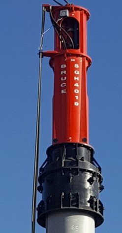
For a BRUCE proposal, consult the official equipment catalogue and request the current model-specific installation information. For background on measuring attachment flow and return pressure, see Webtec’s hydraulic attachment setup guidance.
Frequently asked questions
Can excavator weight alone confirm compatibility?
No. Hydraulic supply, return conditions, mounting, attachment mass, operating configuration and pile-handling requirements must also be checked.
Can a hydraulic breaker circuit run a vibro hammer?
Do not assume so. The circuit must meet the particular vibro hammer’s flow, pressure, return, control and drain requirements. Review the actual installation with the manufacturers.
What should I send for a compatibility review?
Send the excavator model and configuration, auxiliary-circuit details, available test results, mounting drawings and pile information. Identify any unknown values.
Request a BRUCE carrier compatibility review
Provide the carrier configuration, hydraulic information and pile drawing. Ask PowerQuip to identify the applicable equipment configuration and any information still needed.
Send Carrier and Hydraulic Details